EP0146079B1 - Gas-permeable refractory plug - Google Patents
Gas-permeable refractory plug Download PDFInfo
- Publication number
- EP0146079B1 EP0146079B1 EP84114799A EP84114799A EP0146079B1 EP 0146079 B1 EP0146079 B1 EP 0146079B1 EP 84114799 A EP84114799 A EP 84114799A EP 84114799 A EP84114799 A EP 84114799A EP 0146079 B1 EP0146079 B1 EP 0146079B1
- Authority
- EP
- European Patent Office
- Prior art keywords
- gas
- refractory material
- plug
- metal
- channels
- Prior art date
- Legal status (The legal status is an assumption and is not a legal conclusion. Google has not performed a legal analysis and makes no representation as to the accuracy of the status listed.)
- Expired - Lifetime
Links
Images

Classifications
-
- C—CHEMISTRY; METALLURGY
- C21—METALLURGY OF IRON
- C21C—PROCESSING OF PIG-IRON, e.g. REFINING, MANUFACTURE OF WROUGHT-IRON OR STEEL; TREATMENT IN MOLTEN STATE OF FERROUS ALLOYS
- C21C5/00—Manufacture of carbon-steel, e.g. plain mild steel, medium carbon steel or cast steel or stainless steel
- C21C5/28—Manufacture of steel in the converter
- C21C5/42—Constructional features of converters
- C21C5/44—Refractory linings
-
- B—PERFORMING OPERATIONS; TRANSPORTING
- B22—CASTING; POWDER METALLURGY
- B22D—CASTING OF METALS; CASTING OF OTHER SUBSTANCES BY THE SAME PROCESSES OR DEVICES
- B22D1/00—Treatment of fused masses in the ladle or the supply runners before casting
- B22D1/002—Treatment with gases
- B22D1/005—Injection assemblies therefor
-
- C—CHEMISTRY; METALLURGY
- C21—METALLURGY OF IRON
- C21C—PROCESSING OF PIG-IRON, e.g. REFINING, MANUFACTURE OF WROUGHT-IRON OR STEEL; TREATMENT IN MOLTEN STATE OF FERROUS ALLOYS
- C21C5/00—Manufacture of carbon-steel, e.g. plain mild steel, medium carbon steel or cast steel or stainless steel
- C21C5/28—Manufacture of steel in the converter
- C21C5/42—Constructional features of converters
- C21C5/46—Details or accessories
- C21C5/48—Bottoms or tuyéres of converters
Definitions
- the invention relates to a gas-permeable structure made of refractory material for blowing gases into metal treatment vessels through the lining thereof.
- the oxygen inflation processes used to fresh iron are improved in such a way that secondary gases, such as nitrogen or argon, are blown in in a controlled manner through the converter base. Blowing of gases into the metal bath through the bottom of the vessel or lining the walls of the vessel can also be considered in the case of oxygen bottom blowing processes and in metal treatment vessels, such as furnace pans, desulfurization pans and the like.
- the gas-permeable structures to be inserted into the lining of the vessel are required to have a durability which corresponds to that of the other refractory lining, since it is difficult to replace worn-out blow-through stones when hot.
- the introduction of gas should be possible both continuously and in particular discontinuously, i.e. the vessel should also be operable without the introduction of gas and, after the gas supply has been switched on again, the structures should be permeable to gas in an unchanged manner.
- the gas permeability of the structure over its service life i.e. over an entire kiln trip, remain essentially the same.
- this structure is provided with a longitudinal metal housing, a free inner end face and a distribution space for gas supply on the outer end face and has local interruptions in the interior for the gas passage between the end faces, which are provided with metal inserts.
- This structure can consist of segments or strips of refractory material and metal inserts in the form of steel sheets in an alternating arrangement.
- these metal inserts can be flat, corrugated, tubular or wire-shaped and have a small wall thickness.
- the gas passes through the narrow gaps that remain free between the refractory material and the metal inserts.
- the refractory material is subjected to the gas pressure, which has a number of disadvantages.
- the metal casing surrounding the refractory material In order to prevent the metal casing surrounding the refractory material from inflating to the side and gas escaping from the side into the surrounding masonry, which could lead to its premature wear, the metal casing made of sheet steel with a relatively thick wall must be made with gas-tight weld seams.
- a mortar layer must be arranged between the refractory material and the metal housing, which layer is difficult to apply.
- a device for blowing purge gas through the bottom or the wall of a converter for metal freshening consisting of a distribution chamber attached to the outer surface of the converter jacket and provided with a gas supply, from which several cylindrical nozzle pipes extend, that pass through the converter jacket, the permanent lining and the wear lining and extend to the inner surface of the lining.
- These nozzle pipes are flattened in the area of the wear chuck by compressing them to a maximum internal width of 1 mm and are expediently embedded in corresponding recesses in the wear chucks.
- installing and renewing such a blowing device is complex and time-consuming, and at best it only appears to be economically feasible for small converters.
- EP-A-70.197 discloses structures for blowing gases into a steel converter, in which nozzle pipes are connected to a distributor in such a way that exposure to gas from the surrounding refractory material is avoided.
- the nozzle tubes can take a slot-like shape.
- the object of the invention is to avoid the aforementioned disadvantages and to provide a blowing device in the form of a gas-permeable refractory structure in which a compression of the gas-conducting metallic channels is avoided.
- the ducts can be compressed, which hinders the passage of gas. This phenomenon cannot be prevented with certainty even by inserting wires into the channels, as is already provided in EP-A-64 449.
- a jacket made of refractory material can consist of ceramic fibers, for example asbestos or cerafelt fibers. It is essential that the material used is both temperature-resistant and, given the different temperatures prevailing in the structure, has properties which ensure that the strains occurring in the structure are absorbed.
- the layer thickness does not exceed a maximum value (approx. 1 mm), since otherwise steel infiltration can occur.
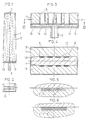
- FIG. 1 shows a for use in a converter bottom g EEI gneter Blasstein in view and in Fig. 2 in top view the upper or inner end surface in Fig.. 3 shows on a larger scale a longitudinal section through the lower or outer part of this blow stone
- FIG. 4 shows a cross section along line IV-IV of FIG. 3 and FIG. 5
- FIG. 6 shows the detail “A” of FIG. 4 in two different embodiments on a further enlarged scale, only FIG. 6 showing the jacket (7) made of refractory material which is essential to the invention.
- Fig. 7 a sink suitable for use in a pan bottom is shown in longitudinal section and in Fig. 8 in a top layer on the upper or inner end face.
- FIG. 9 shows the top view of the upper or inner end face of another embodiment of the sink block according to FIG. 7.
- the blow stone shown in FIGS. 1 to 6 is suitable for use in a converter base.
- the refractory material is exposed on its upper end face 11, which faces the interior of the converter when installed.
- On the opposite end face 12 there is a gas distribution space 13 which extends over the entire end face 12 and which is delimited by an inner sheet metal plate 14 lying against the refractory material, narrow lateral sheet metal strips 15 and an outer base plate 16.
- a tubular gas supply 3 is attached.
- the four side surfaces of the blowing stone 1 are covered by a metal housing 17.
- the refractory material of the blow stone 1 consists of three prefabricated sections or segments 18, 19 which are held together by the metal housing 17. Two of these segments, namely the two segments 18, are provided on a larger longitudinal side surface with four flat grooves 4 each, which run from the outer and lower end surface 12 of the refractory material to the inner or upper end surface 11 and thus extend over the entire length of the refractory Stretch material.
- the grooves 4 can be formed in the segments 18 during their manufacture by appropriate design of the die or they can z. B. can be incorporated by milling, planing or cutting.
- narrow metallic channels 5 are inserted, which are gas-tight on the sides.
- These channels 5 are preferably made of sheet steel or copper and have a wall thickness of, for example, about 0.5 to 1 mm and an inside width of the order of 0.3 to 1 mm.
- the channels 5 are inserted into corresponding openings in the inner plate 14 of the gas distribution space 13 and with the plate 14 z.
- Compliance with the channel width in the order of magnitude of 0.3 to 1 mm ensures that, on the one hand, the required amount of gas can be conveyed through the channels 5 into the metal bath and that, on the other hand, if the gas supply is switched off temporarily, there is no permanent injury to the channels due to penetration Metal melt comes, but that the channels can be blown free after switching on the gas supply.
- the channels 5 can be provided with known inserts of one or more metal wires 6, as shown in FIG. 5.
- the measure according to the invention for preventing the ducts from being compressed as a result of the thermal expansion of the refractory material is to coat the ducts 5 on their outside with a compressible refractory fibrous material 7, preferably to wrap them around, as is illustrated in FIG. 6. Due to its compressibility, the fibrous material 7 can absorb the thermal expansion of the refractory material, so that there is no compression of the channels 5.
- FIG. 7 to 9 show a sink 2 suitable for use in a pan bottom. It has the shape of a truncated cone, which, in cooperation with a known perforated brick with a truncated cone-shaped opening, makes it easy to replace this sink.
- a smaller end face 21 which is installed against the inside of the pan the refractory material is exposed.
- the refractory material has a frustoconical central recess 20, in which a gas distribution space 23 is arranged.
- the refractory material of the sink 2 can consist of refractory mass.
- the metal structure consisting of the channels 5, the gas distribution space 23, the base plate 26 and the metal housing 27 is first produced and its free space is filled with a refractory casting or ramming mass, so that a refractory mass body 28 is formed in which the channels are embedded. Since not only the subsequent thermal expansion of the refractory material acts on the channels 5, but also the compression pressure for the refractory mass, the risk of compression is particularly great here. Therefore, in this case, the embodiment according to FIG. 6, ie. H. coating, e.g. B. wrapping with a compressible refractory fiber 7th
- the refractory material of the sink 2 can also consist of several prefabricated segments. According to FIG. 9, there are two such segments 29 in the form of half truncated cones, which are provided with slots or grooves 4 ′, which complement one another in pairs, for receiving the channels 5.
- the gas distribution space 23 of the sink 2 could extend over the entire outer end face 22, or the gas distribution space 13 of the blow stone 1 could be limited to a central area arranged in a recess in the refractory material.
- the refractory material of the structure according to the invention can consist, for example, of sintered or melted magnesia, of a mixture of magnesia or chrome ore, of pre-reacted magnesia chrome ore sintered or melted material or of high alumina material. Enrichment of the refractory material with a carbon carrier is also possible.
- the material can be used in the form of baked segments or it can be chemically bonded, pitch bonded or resin bonded. Subsequent impregnation of the prefabricated burned or bonded segments with a carbon carrier, such as tar, pitch or synthetic resin, is also possible.
Abstract
Description
Die Erfindung betrifft einen gasdurchlässigen Baukörper aus feuerfestem Material zum Einblasen von Gasen in Metallbehandlungsgefässe durch deren Auskleidung hindurch.The invention relates to a gas-permeable structure made of refractory material for blowing gases into metal treatment vessels through the lining thereof.
Die zum Roheisenfrischen dienenden Sauerstoff-Aufblasverfahren wurden in metallurgischer Hinsicht dahingehend verbessert, dass durch den Konverterboden Sekundärgase, wie Stickstoff oder Argon, gesteuert eingeblasen werden. Auch bei Sauerstoff-Bodenblasverfahren sowie in Metallbehandlungsgefässen, wie etwa Ofenpfannen, Entschwefelungspfannen u.dgl., kommt das Einblasen von Gasen in das Metallbad durch den Gefässboden oder die Auskleidung der Gefässwände hindurch in Betracht.In terms of metallurgy, the oxygen inflation processes used to fresh iron are improved in such a way that secondary gases, such as nitrogen or argon, are blown in in a controlled manner through the converter base. Blowing of gases into the metal bath through the bottom of the vessel or lining the walls of the vessel can also be considered in the case of oxygen bottom blowing processes and in metal treatment vessels, such as furnace pans, desulfurization pans and the like.
An die in die Auskleidung des Gefässes einzusetzenden gasdurchlässigen Baukörper wird die Forderung gestellt, dass ihre Haltbarkeit derjenigen der übrigen feuerfesten Auskleidung entspricht, da ein Auswechseln verschlissener Gasdurchblassteine im heissen Zustand schwierig ist. Ferner soll die Gaseinleitung sowohl kontinuierlich als insbesondere auch diskontinuierlich möglich sein, d.h. das Gefäss soll auch ohne Gaseinleitung betreibbar sein und nach dem Wiedereinschalten der Gaszufuhr sollen die Baukörper in unveränderter Weise gasdurchlässig sein. Ausserdem soll die Gasdurchlässigkeit der Baukörper über ihre Gebrauchsdauer, d.h. über eine ganze Ofenreise, im wesentlichen gleich bleiben.The gas-permeable structures to be inserted into the lining of the vessel are required to have a durability which corresponds to that of the other refractory lining, since it is difficult to replace worn-out blow-through stones when hot. Furthermore, the introduction of gas should be possible both continuously and in particular discontinuously, i.e. the vessel should also be operable without the introduction of gas and, after the gas supply has been switched on again, the structures should be permeable to gas in an unchanged manner. In addition, the gas permeability of the structure over its service life, i.e. over an entire kiln trip, remain essentially the same.
Diese Forderungen werden durch den feuerfesten gasdurchlässigen Baukörper erfüllt, welcher in der EP-A-21 861 beschrieben ist. Nach einer Ausführungsform ist dieser Baukörper mit einem längsseitigen Metallgehäuse, einer freien inneren Stimfläche und einem Verteilungsraum zur Gaszuführung an der äusseren Stirnfläche versehen und weist in seinem Inneren für den Gasdurchgang zwischen den Stirnflächen verlaufende, lokale Unterbrechungen auf, die mit Metalleinlagen versehen sind. Dieser Baukörper kann aus Segmenten oder Streifen aus feuerfestem Material und Metalleinlagen in Form von Stahlblechen in abwechselnder Anordnung bestehen. Gemäss der genannten EP-A-21 861 können diese Metalleinlagen eben, gewellt, rohrförmig oder drahtförmig sein und weisen eine geringe Wandstärke auf.These requirements are met by the refractory gas-permeable structure, which is described in EP-A-21 861. According to one embodiment, this structure is provided with a longitudinal metal housing, a free inner end face and a distribution space for gas supply on the outer end face and has local interruptions in the interior for the gas passage between the end faces, which are provided with metal inserts. This structure can consist of segments or strips of refractory material and metal inserts in the form of steel sheets in an alternating arrangement. According to EP-A-21 861 mentioned, these metal inserts can be flat, corrugated, tubular or wire-shaped and have a small wall thickness.
Bei all diesen Baukörpem erfolgt der Gasdurchgang durch die engen Spalte, die zwischen dem feuerfesten Material und den Metalleinlagen freibleiben. Dabei wird das feuerfeste Material mit dem Gasdruck beaufschlagt, was eine Reihe von Nachteilen mit sich bringt. Um ein seitliches Aufblähen des das feuerfeste Material umgebenden Metallgehäuses und einen seitlichen Gasaustritt in das umgebende Mauerwerk, das zu dessen vorzeitigem Verschleiss führen könnte, zu verhindern, muss das Metallgehäuse aus Stahlblech von relativ dicker Wandstärke unter Anbringung von gasdichten Schweissnähten ausgeführt werden. Um den unerwünschten, weil unkontrollierbaren Gasdurchtritt längs der Innenwand des Metallgehäuses zu verhindern, muss zwischen dem feuerfesten Material und dem Metallgehäuse eine Mörteischicht angeordnet werden, welche schwierig einzubringen ist. Bei Verwendung von Stickstoff als Spülgas kann es ausserdem zu einem Aufsticken und, bedingt durch das häufig kohlenstoffhaltige feuerfeste Material, zu einem gleichzeitigen Aufkohlen des Metallgehäuses kommen, was beides dazu führt, dass das Metall spröde und rissanfällig wird, wodurch es zur Beeinträchtigung der Gasdichtheit kommen kann. Bei Verwendung von CO2 als Spülgas hingegen wird das kohlenstoffhaltige feuerfeste Material entkohlt; dieses muss daher allseitig durch Blechauflagen oder durch Anstriche geschützt werden.In all of these structures, the gas passes through the narrow gaps that remain free between the refractory material and the metal inserts. The refractory material is subjected to the gas pressure, which has a number of disadvantages. In order to prevent the metal casing surrounding the refractory material from inflating to the side and gas escaping from the side into the surrounding masonry, which could lead to its premature wear, the metal casing made of sheet steel with a relatively thick wall must be made with gas-tight weld seams. In order to prevent the undesirable, because uncontrollable, gas passage along the inner wall of the metal housing, a mortar layer must be arranged between the refractory material and the metal housing, which layer is difficult to apply. If nitrogen is used as the purge gas, embroidery and, due to the often carbon-containing refractory material, carburization of the metal housing can occur, both of which lead to the metal becoming brittle and susceptible to cracking, which leads to impairment of the gas tightness can. When using CO 2 as the purge gas, however, the carbon-containing refractory material is decarburized; This must therefore be protected on all sides by sheet metal supports or by painting.
Ferner besteht die Gefahr, dass das feuerfeste Material durch den Gasdruck aus dem Metallgehäuse heraus- und in das Metallbad hineingedrückt wird, was zu einem Durchbruch des Metallbades durch die Auskleidung führt.There is also the risk that the refractory material is pressed out of the metal housing and into the metal bath by the gas pressure, which leads to a breakthrough of the metal bath through the lining.
Aus der EP-A-64 449 ist eine Einrichtung zum Einblasen von Spülgas durch den Boden oder die Wand eines Konverters zum Metallfrischen bekannt, bestehend aus einer an der Aussenfläche des Konvertermantels befestigten, mit einer Gaszuführung versehenen Verteilungskammer, von der mehrere zylindrische Düsenrohre ausgehen, die durch den Konvertermantel, das Dauerfutter und das Verschleissfutter hindurchgehen und bis zur Innenfläche der Auskleidung reichen. Diese Düsenrohre sind im Bereich des Verschleissfutters durch Zusammendrücken auf maximal 1 mm Innenbreite abgeflacht und sind zweckmässig in entsprechende Ausnehmungen der Verschleissfuttersteine eingebettet. Der Einbau und die Erneuerung einer derartigen Blaseinrichtung ist jedoch aufwendig und zeitraubend, und sie erscheint bestenfalls nur bei kleinen Konvertern wirtschaftlich einsetzbar.From EP-A-64 449 a device for blowing purge gas through the bottom or the wall of a converter for metal freshening is known, consisting of a distribution chamber attached to the outer surface of the converter jacket and provided with a gas supply, from which several cylindrical nozzle pipes extend, that pass through the converter jacket, the permanent lining and the wear lining and extend to the inner surface of the lining. These nozzle pipes are flattened in the area of the wear chuck by compressing them to a maximum internal width of 1 mm and are expediently embedded in corresponding recesses in the wear chucks. However, installing and renewing such a blowing device is complex and time-consuming, and at best it only appears to be economically feasible for small converters.
Weiterhin sind aus der EP-A-70.197 Baukörper zum Einblasen von Gasen in einen Stahlkonverter bekannt, bei denen Düsenrohre so mit einem Verteiler verbunden sind, dass eine Beaufschlagung vom umliegenden feuerfesten Material mit Gasdruck vermieden wird. Die Düsenrohre können eine schlitzförmige Gestalt annehmen.Furthermore, EP-A-70.197 discloses structures for blowing gases into a steel converter, in which nozzle pipes are connected to a distributor in such a way that exposure to gas from the surrounding refractory material is avoided. The nozzle tubes can take a slot-like shape.
Aufgabe der Erfindung ist es, die vorgenannten Nachteile zu vermeiden und eine Blaseinrichtung in Form eines gasdurchlässigen feuerfesten Baukörpers zu schaffen, bei dem ein Zusammendrücken der Gas leitenden metallischen Kanäle vermieden wird.The object of the invention is to avoid the aforementioned disadvantages and to provide a blowing device in the form of a gas-permeable refractory structure in which a compression of the gas-conducting metallic channels is avoided.
Nach der Erfindung wird diese Aufgabe durch den kennzeichnenden Teil des Anspruchs 1 gelöst. Vorteilhafte Ausgestaltungen der Erfindung sind in den abhängigen Ansprüchen wiedergegeben.According to the invention, this object is achieved by the characterizing part of claim 1. Advantageous embodiments of the invention are given in the dependent claims.
Wenn die metallischen Kanäle dünnwandig sind und das feuerfeste Material einer starken Wärmeausdehnung unterliegt, wie dies bei Magnesitmaterial der Fall ist, kann es dazu kommen, dass die Kanäle zusammengedrückt werden, wodurch der Gasdurchgang behindert wird. Diese Erscheinung kann auch durch das Einlegen von Drähten in die Kanäle, wie dies schon in der EP-A-64 449 vorgesehen wird, nicht mit Sicherheit verhindert werden. In diesem Fall empfiehlt es sich, die metallischen Kanäle an ihrer Aussenseite mit einem Mantel aus feuerfestem Material zu bekleiden. Dieser Mantel kann aus keramischen Fasern, bspw. Asbest- oder Cerafelt-Fasern bestehen. Wesentlich ist, dass das verwendete Material sowohl temperaturbeständig ist als auch bei den in dem Baukörper herrschenden unterschiedlichen Temperaturen Eigenschaften aufweist, die ein Auffangen der im Baukörper auftretenden Dehnungen gewährleisten. Diese Eigenschaften können zur kalten Seite des Baukörpers hin vorrangig von elastischer Natur sein, während zur warmen Seite hin (Stahlbad) ein teilweises Sintern stattfinden kann. Die durch das Sintern bedingte Volumenverminderung wird dann durch die Ausdehnung des umgebenden feuerfesten Materials und des metallischen Kanals ausgeglichen. Das Material kann in Mattenform um die Kanäle gewickelt werden. Zu beachten ist, dass die Schichtdicke einen Maximalwert (etwa 1 mm) nicht übersteigt, da anders eine Stahlinfiltration auftreten kann.If the metallic channels are thin-walled and the refractory material is subject to high thermal expansion, as is the case with Ma gnesite material, the ducts can be compressed, which hinders the passage of gas. This phenomenon cannot be prevented with certainty even by inserting wires into the channels, as is already provided in EP-A-64 449. In this case, it is advisable to cover the metallic channels on the outside with a jacket made of refractory material. This jacket can consist of ceramic fibers, for example asbestos or cerafelt fibers. It is essential that the material used is both temperature-resistant and, given the different temperatures prevailing in the structure, has properties which ensure that the strains occurring in the structure are absorbed. On the cold side of the building, these properties can be primarily of an elastic nature, while on the warm side (steel bath), partial sintering can take place. The volume reduction due to the sintering is then compensated for by the expansion of the surrounding refractory material and the metallic channel. The material can be wrapped around the channels in mat form. It should be noted that the layer thickness does not exceed a maximum value (approx. 1 mm), since otherwise steel infiltration can occur.
Die Erfindung wird anhand der schematischen Zeichnungen näher erläutert. In diesen ist in Fig. 1 ein zum Einsatz in einen Konverterboden geei- gneter Blasstein in Ansicht und in Fig. 2 in Draufsicht auf die obere oder innere Stirnfläche dargestellt. Fig. 3 zeigt in grösserem Masstab einen Längsschnitt durch den unteren oder äusseren Teil dieses Blassteines, Fig. 4 einen Querschnitt nach Linie IV-IV der Fig. 3 und Fig. 5 sowie Fig. 6 zeigen das Detail « A » der Fig. 4 in zwei verschiedenen Ausführungsformen in abermals vergrössertem Masstab, wobei lediglich Fig. 6 den erfindungswesentlichen Mantel (7) aus feuerfestem Material zeigt. In Fig. 7 ist ein zum Einsatz in einen Pfannenboden geeigneter Spülstein im Längsschnitt und in Fig. 8 in Draufschicht auf die obere oder innere Stirnfläche dargestellt. Fig. 9 zeigt die Draufsicht auf die obere oder innere Stirnfläche einer anderen Ausführungsform des Spülsteines nach Fig. 7.The invention is explained in more detail with reference to the schematic drawings. In this 1 shows a for use in a converter bottom g EEI gneter Blasstein in view and in Fig. 2 in top view the upper or inner end surface in Fig.. 3 shows on a larger scale a longitudinal section through the lower or outer part of this blow stone, FIG. 4 shows a cross section along line IV-IV of FIG. 3 and FIG. 5 and FIG. 6 shows the detail “A” of FIG. 4 in two different embodiments on a further enlarged scale, only FIG. 6 showing the jacket (7) made of refractory material which is essential to the invention. In Fig. 7 a sink suitable for use in a pan bottom is shown in longitudinal section and in Fig. 8 in a top layer on the upper or inner end face. FIG. 9 shows the top view of the upper or inner end face of another embodiment of the sink block according to FIG. 7.
Der in Fig. 1 bis 6 dargestellte Blasstein ist zum Einsatz in einen Konverterboden geeignet. An seiner oberen, im eingebauten Zustand gegen das Konverterinnere weisenden Stirnfläche 11 liegt das feuerfeste Material frei. An der gegenüberliegenden Stirnfläche 12 ist ein sich über die ganze Stirnfläche 12 erstreckender Gasverteilungsraum 13 angeordnet, der von einer am feuerfesten Material anliegenden inneren Blechplatte 14, schmalen seitlichen Blechstreifen 15 und einer äusseren Grundplatte 16 begrenzt ist. In letzterer ist eine rohrförmige Gaszuführung 3 befestigt. Die vier Seitenflächen des Blassteines 1 sind von einem Metallgehäuse 17 bedeckt.The blow stone shown in FIGS. 1 to 6 is suitable for use in a converter base. The refractory material is exposed on its
Das feuerfeste Material des Blassteines 1 besteht aus drei vorgefertigten Abschnitten oder Segmenten 18, 19, die von dem Metallgehäuse 17 zusammengehalten sind. Zwei dieser Segmente, nämlich die beiden Segmente 18, sind an einer grösseren Längsseitenfläche mit je vier flachen Nuten 4 versehen, die von der äusseren und unteren Stirnfläche 12 des feuerfesten Materials zur inneren oder oberen Stirnfläche 11 verlaufen und sich somit über die gesamte Länge des feuerfesten Materials erstrecken. Die Nuten 4 können in den Segmenten 18 während deren Fertigung durch entsprechende Ausgestaltung der Pressform ausgebildet werden oder sie können in die fertigen Segmente z. B. durch Fräsen, Hobeln oder Schneiden eingearbeitet werden.The refractory material of the blow stone 1 consists of three prefabricated sections or
In die Nuten 4 sind schmale metallische Kanäle 5 eingelegt, die nach den Seiten hin gasdicht geschlossen sind. Diese Kanäle 5 sind vorzugsweise aus Stahl- oder Kupferblech gefertigt und weisen eine Wandstärke beispielsweise von etwa 0,5 bis 1 mm und eine Innenweite in der Grössenordnung von 0,3 bis 1 mm auf. Die Kanäle 5 sind in entsprechende Öffnungen der inneren Blechplatte 14 des Gasverteilungsraumes 13 eingesteckt und mit der Blechplatte 14 z. B. durch Löten, Schweissen oder Kleben gasdicht verbunden. Durch diese Massnahme wird erreicht, dass das feuerfeste Material und das äussere Metallgehäuse 17 frei von einer Beaufschlagung durch den Gasdruck des Behandlungsgases bleiben, welches durch die Gaszuführung 3 in den Gasverteilungsraum 13 eintritt und von diesem durch die schmalen Kanäle 5 in das Metallbad gelangt.In the
Die Einhaltung der Kanalweite in der Grössenordnung von 0,3 bis 1 mm stellt sicher, dass einerseits die erforderliche Gasmenge durch die Kanäle 5 in das Metallbad gefördert werden kann und, dass es andererseits bei zeitweisem Abschalten der Gaszufuhr zu keiner dauernden Verletzung der Kanäle durch eindringende Metallschmelze kommt, sondern, dass die Kanäle nach Wiedereinschalten der Gaszufuhr freigeblasen werden können.Compliance with the channel width in the order of magnitude of 0.3 to 1 mm ensures that, on the one hand, the required amount of gas can be conveyed through the
Um zu verhindern, dass die Kanäle durch das sich in der Wärme dehnende feuerfeste Material zusammengedrückt werden, können die Kanäle 5 mit an sich bekannten Einlagen eines oder mehrerer Metalldrähte 6 versehen sein, wie dies in Fig. 5 dargestellt ist. Die erfindungsgemässe Massnahme zur Verhinderung des Zusammendrückens der Kanäle infolge der Wärmedehnung des feuerfesten Materials besteht darin, die Kanäle 5 an ihrer Aussenseite mit einem komprimierbaren feuerfesten Faserstoff 7 zu beschichten, vorzugsweise zu umwickeln, wie dies in Fig. 6 veranschaulicht ist. Der Faserstoff 7 kann durch seine Kompressibilität die Wärmedehnung des feuerfesten Materials aufnehmen, so dass es zu keinem Zusammendrücken der Kanäle 5 kommt.In order to prevent the channels from being pressed together by the refractory material that expands in the heat, the
In Fig. 7 bis 9 ist ein zum Einsatz in einen Pfannenboden geeigneter Spülstein 2 dargestellt. Er weist Kegelstumpfform auf, was im Zusammenwirken mit einem an sich bekannten korrespondierenden Lochstein mit kegelstumpfförmiger Öffnung ein leichtes Auswechseln dieses Spülsteines ermöglicht. An einer kleineren Stirnfläche 21, die im Einbauzustand gegen das Pfanneninnere weist, liegt das feuerfeste Material frei. An der gegenüberliegenden grösseren Stirnfläche 22 weist das feuerfeste Material eine kegelstumpfförmige zentrale Vertiefung 20 auf, in welcher ein Gasverteilungsraum 23 angeordnet ist. Dieser ist gegen das feuerfeste Material durch eine innere Blechplatte 24 und einen seitlichen Blechring 25 gasdicht abgegrenzt und nach aussen durch eine Grundplatte 26 abgeschlossen, die sich über die gesamte grössere Stimfläche 22 erstreckt und in der eine zentrale, rohrförmige Gaszuführung 3 mündet. Die kegelstumpfförmige Mantelfläche des Spülsteines 2 ist von einem Metallgehäuse 27 bedeckt. In das feuerfeste Material des Spülsteines 2 sind drei schmale metallische Kanäle 5 der vorhin beschriebenen Art eingebettet, die sich vom Gasverteilungsraum 23 zur freien Stirnfläche 21 erstrecken und durch die das Spülgas ins Pfanneninnere gefördert werden kann. Die Kanäle 5, die, wie in Fig. 8 und 9 veranschaulicht, unterschiedliche Breite haben können, sind in der inneren Blechplatte 24 des Gasverteilungsraumes 23 gasdicht befestigt, um das feuerfeste Material und das Metallgehäuse 27 drucklos zu machen, d. h. von einer Beaufschlagung durch den Gasdruck des Spülgases freizuhalten.7 to 9 show a
Nach der in Fig. 8 gezeigten Ausführungsform kann das feuerfeste Material des Spülsteines 2 aus feuerfester Masse bestehen. In diesem Fall wird zuerst das aus den Kanälen 5, des Gasverteilungsraum 23, der Grundplatte 26 und dem Metallgehäuse 27 bestehende Metallgebilde hergestellt und dessen freier Raum mit einer feuerfesten Giess- oder Stampfmasse ausgefüllt, so dass ein feuerfester Massenkörper 28 entsteht, in dem die Kanäle eingebettet sind. Da auf die Kanäle 5 nicht nur die spätere Wärmedehnung des feuerfesten Materials, sondern auch der Verdichtungsdruck für die feuerfeste Masse wirkt, ist die Gefahr des Zusammendrückens hier besonders gross. Daher empfiehlt sich in diesem Fall für die Kanäle 5 die Ausführungsart nach Fig. 6, d. h. das Beschichten, z. B. Umwickeln, mit einem komprimierbaren feuerfesten Faserstoff 7.According to the embodiment shown in Fig. 8, the refractory material of the
Nach einer anderen Ausführungsform kann das feuerfeste Material des Spülsteines 2 auch aus mehreren vorgefertigten Segmenten bestehen. Gemäss Fig. 9 sind es zwei solcher Segmente 29 in Form von halben Kegelstümpfen, die mit einander paarweise ergänzenden Schlitzen oder Nuten 4' zur Aufnahme der Kanäle 5 versehen sind.According to another embodiment, the refractory material of the
Es sind auch Abänderungen der gezeichneten Ausführungsbeispiele möglich. So könnte sich der Gasverteilungsraum 23 des Spülsteines 2 über die gesamte äussere Stirnfläche 22 erstrecken oder der Gasverteilungsraum 13 des Blassteines 1 könnte auf einen zentralen, in einer Vertiefung des feuerfesten Materials angeordneten Bereich beschränkt sein. Das feuerfeste Material des erfindungsgemässen Baukörpers kann beispielsweise aus Sinter- oder Schmelzmagnesia, aus einer Mischung von Magnesia oder Chromerz, aus vorreagiertem Magnesiachromerz-Sinter- oder Schmelzmaterial oder aus Hochtonerdenmaterial bestehen. Auch eine Anreicherung des feuerfesten Materials mit einem Kohlenstoffträger ist möglich. Das Material kann in Form gebrannter Segmente eingesetzt werden oder es kann chemisch gebunden, pechgebunden oder kunstharzgebunden sein. Auch eine nachträgliche Tränkung der vorgefertigten gebrannten oder gebundenen Segmente mit einem Kohlenstoffträger, wie Teer, Pech oder Kunstharz, ist möglich.Modifications to the illustrated exemplary embodiments are also possible. For example, the
Claims (10)
Priority Applications (1)
| Application Number | Priority Date | Filing Date | Title |
|---|---|---|---|
| AT84114799T ATE50797T1 (en) | 1983-12-12 | 1984-12-05 | GAS-PERMEABLE STRUCTURE MADE OF FIREPROOF MATERIAL. |
Applications Claiming Priority (2)
| Application Number | Priority Date | Filing Date | Title |
|---|---|---|---|
| LU85131 | 1983-12-12 | ||
| LU85131A LU85131A1 (en) | 1983-12-12 | 1983-12-12 | GAS-PERMEABLE CONSTRUCTION BODY MADE OF FIRE-RESISTANT MATERIAL |
Publications (3)
| Publication Number | Publication Date |
|---|---|
| EP0146079A2 EP0146079A2 (en) | 1985-06-26 |
| EP0146079A3 EP0146079A3 (en) | 1987-01-07 |
| EP0146079B1 true EP0146079B1 (en) | 1990-03-07 |
Family
ID=19730188
Family Applications (1)
| Application Number | Title | Priority Date | Filing Date |
|---|---|---|---|
| EP84114799A Expired - Lifetime EP0146079B1 (en) | 1983-12-12 | 1984-12-05 | Gas-permeable refractory plug |
Country Status (13)
| Country | Link |
|---|---|
| US (1) | US4647020A (en) |
| EP (1) | EP0146079B1 (en) |
| JP (1) | JPS60149709A (en) |
| KR (1) | KR850004990A (en) |
| AT (1) | ATE50797T1 (en) |
| AU (1) | AU566336B2 (en) |
| BR (1) | BR8406349A (en) |
| CA (1) | CA1247861A (en) |
| DE (1) | DE3481527D1 (en) |
| ES (1) | ES291744Y (en) |
| IN (1) | IN162802B (en) |
| LU (1) | LU85131A1 (en) |
| ZA (1) | ZA849690B (en) |
Cited By (5)
| Publication number | Priority date | Publication date | Assignee | Title |
|---|---|---|---|---|
| DE4101833A1 (en) * | 1991-01-23 | 1992-08-06 | Hoesch Stahl Ag | Lifting gas jet - has coaxial slit in inner wall cladding of trunk of vacuum assembly to counteract pressure changes |
| DE4335643C1 (en) * | 1993-10-15 | 1994-10-27 | Mannesmann Ag | Method and apparatus for introducing gases into metal melts |
| DE4411538C1 (en) * | 1994-04-02 | 1995-12-14 | Didier Werke Ag | Method for producing a gas and / or solid-state blowing device for metallurgical vessels, and blowing device produced according to the method |
| DE19542446A1 (en) * | 1995-11-14 | 1997-05-15 | Lorenz Doetsch | Fireproof molded panels with gas routing channels |
| CN100469899C (en) * | 2003-06-16 | 2009-03-18 | 德国技术通信进出口公司 | Tuyere device for introducing gaseous media under a liquid-metal layer |
Families Citing this family (14)
| Publication number | Priority date | Publication date | Assignee | Title |
|---|---|---|---|---|
| DE3538498A1 (en) * | 1985-10-30 | 1987-05-07 | Didier Werke Ag | INJECTING DEVICE FOR METALLURGICAL VESSELS |
| NL8600608A (en) * | 1986-03-10 | 1987-10-01 | Hoogovens Groep Bv | CONVERTER FOR PREPARING STEEL. |
| DE3625117C1 (en) * | 1986-07-25 | 1987-11-26 | Didier Werke Ag | Gas-flushing cone |
| US4741515A (en) * | 1986-10-20 | 1988-05-03 | Bethlehem Steel Corporation | Apparatus for introducing gas into a metallurgical vessel |
| LU86816A1 (en) * | 1987-03-19 | 1988-11-17 | Arbed | DEVICE FOR DRAINING METALLURGICAL CONTAINERS |
| DE3734713A1 (en) * | 1987-10-14 | 1989-04-27 | Pa Ha Ge Huetten Und Giesserei | COOLING STONE FOR METALLURGICAL VESSELS |
| US4836433A (en) * | 1988-05-13 | 1989-06-06 | Insul Company, Inc. | Device for introducing stirring gas into molten metal in metered amount |
| US4840356A (en) * | 1988-06-13 | 1989-06-20 | Labate Michael D | Externally replaceable stirring plug for molten metal vessels |
| DE4022949C1 (en) * | 1990-07-19 | 1991-07-11 | Radex-Heraklith Industriebeteiligungs Ag, Wien, At | |
| JPH0510443U (en) * | 1991-07-29 | 1993-02-09 | 東京窯業株式会社 | Gas injection plug |
| US5249778A (en) * | 1992-04-14 | 1993-10-05 | Dolomitwerke Gmbh | Gas stir plug device with visual wear indicator |
| CA2073219C (en) * | 1992-07-06 | 1995-12-19 | Keizo Aramaki | Refractory for gas blowing for molten metal refining vessel |
| CN110066906A (en) * | 2019-06-06 | 2019-07-30 | 洛阳利尔耐火材料有限公司 | A kind of one-pass molding integral air brick, molding die and forming method |
| LU500076B1 (en) * | 2021-04-23 | 2022-10-24 | Exus Refractories Spa | Gas purging plug for a metallurgical container |
Family Cites Families (17)
| Publication number | Priority date | Publication date | Assignee | Title |
|---|---|---|---|---|
| AT288952B (en) * | 1968-12-06 | 1971-03-25 | Veitscher Magnesitwerke Ag | Refractory lining with expansion compensation and process for the production of an insulating compound for such linings |
| US4238121A (en) * | 1977-10-07 | 1980-12-09 | Kawasaki Steel Corporation | Hearth structure of an oxygen-bottom-blowing converter |
| CA1130560A (en) * | 1978-08-28 | 1982-08-31 | Yoshihiro Hayashi | Lance pipe for refining and refining process of molten metal |
| FR2455008A1 (en) * | 1979-04-25 | 1980-11-21 | Siderurgie Fse Inst Rech | REFRACTORY PIECE WITH SELECTIVE AND ORIENTED PERMEABILITY FOR THE INSUFFLATION OF A FLUID |
| CS241483B2 (en) * | 1980-06-25 | 1986-03-13 | Arbed | Refractory building body |
| LU82597A1 (en) * | 1980-07-09 | 1982-02-17 | Arbed | FIRE-RESISTANT, GAS-PERMEABLE CONSTRUCTION |
| FR2504664A1 (en) * | 1981-04-24 | 1982-10-29 | Francais Aciers Speciaux | DEVICE FOR BLOWING BREWING GAS IN A METAL REFINING CONVERTER |
| GB2102926B (en) * | 1981-06-03 | 1985-05-15 | Nippon Kokan Kk | Gas blowing nozzle, and production and usage thereof |
| AU541441B2 (en) * | 1981-07-15 | 1985-01-10 | Nippon Steel Corporation | Bottom blowing nozzle embedded in a refractory block |
| JPS5839719A (en) * | 1981-09-02 | 1983-03-08 | Nippon Steel Corp | Formation of nozzle for bottom blowing of gas |
| JPS5839720A (en) * | 1981-09-02 | 1983-03-08 | Nippon Steel Corp | Protecting method for air permeable refractory of bottom blown converter |
| US4462576A (en) * | 1982-02-24 | 1984-07-31 | Didier-Werke Ag | Apparatus for supplying gas through the wall of a metallurgical container |
| JPS58167717A (en) * | 1982-03-29 | 1983-10-04 | Nippon Kokan Kk <Nkk> | Nozzle for refining molten metal |
| WO1983003427A1 (en) * | 1982-03-29 | 1983-03-29 | Miyawaki, Yoshiharu | Bottom blowing gas nozzle in molten metal refining furnace and method of melting steel using the same nozzle |
| LU84167A1 (en) * | 1982-05-25 | 1983-11-23 | Arbed | FIRE-RESISTANT, GAS-PERMEABLE CONSTRUCTION |
| JPS58210112A (en) * | 1982-05-31 | 1983-12-07 | Nippon Steel Corp | Gas blow nozzle |
| JPS5920418A (en) * | 1982-07-27 | 1984-02-02 | Tokyo Yogyo Co Ltd | Immersed riser of rh degassing apparatus |
-
1983
- 1983-12-12 LU LU85131A patent/LU85131A1/en unknown
-
1984
- 1984-12-05 AT AT84114799T patent/ATE50797T1/en not_active IP Right Cessation
- 1984-12-05 EP EP84114799A patent/EP0146079B1/en not_active Expired - Lifetime
- 1984-12-05 DE DE8484114799T patent/DE3481527D1/en not_active Expired - Lifetime
- 1984-12-10 AU AU36455/84A patent/AU566336B2/en not_active Ceased
- 1984-12-11 IN IN975/MAS/84A patent/IN162802B/en unknown
- 1984-12-11 BR BR8406349A patent/BR8406349A/en unknown
- 1984-12-12 CA CA000469956A patent/CA1247861A/en not_active Expired
- 1984-12-12 KR KR1019840007862A patent/KR850004990A/en not_active Application Discontinuation
- 1984-12-12 ZA ZA849690A patent/ZA849690B/en unknown
- 1984-12-12 US US06/681,215 patent/US4647020A/en not_active Expired - Fee Related
- 1984-12-12 ES ES1984291744U patent/ES291744Y/en not_active Expired
- 1984-12-12 JP JP59262643A patent/JPS60149709A/en active Pending
Cited By (6)
| Publication number | Priority date | Publication date | Assignee | Title |
|---|---|---|---|---|
| DE4101833A1 (en) * | 1991-01-23 | 1992-08-06 | Hoesch Stahl Ag | Lifting gas jet - has coaxial slit in inner wall cladding of trunk of vacuum assembly to counteract pressure changes |
| DE4335643C1 (en) * | 1993-10-15 | 1994-10-27 | Mannesmann Ag | Method and apparatus for introducing gases into metal melts |
| DE4411538C1 (en) * | 1994-04-02 | 1995-12-14 | Didier Werke Ag | Method for producing a gas and / or solid-state blowing device for metallurgical vessels, and blowing device produced according to the method |
| DE19542446A1 (en) * | 1995-11-14 | 1997-05-15 | Lorenz Doetsch | Fireproof molded panels with gas routing channels |
| DE19542446C2 (en) * | 1995-11-14 | 1998-05-28 | Doetsch Geb Richard Marie Luis | Fireproof molded panels with gas routing channels |
| CN100469899C (en) * | 2003-06-16 | 2009-03-18 | 德国技术通信进出口公司 | Tuyere device for introducing gaseous media under a liquid-metal layer |
Also Published As
| Publication number | Publication date |
|---|---|
| CA1247861A (en) | 1989-01-03 |
| AU566336B2 (en) | 1987-10-15 |
| EP0146079A3 (en) | 1987-01-07 |
| KR850004990A (en) | 1985-08-19 |
| ZA849690B (en) | 1985-07-31 |
| DE3481527D1 (en) | 1990-04-12 |
| IN162802B (en) | 1988-07-09 |
| ATE50797T1 (en) | 1990-03-15 |
| ES291744Y (en) | 1987-03-01 |
| AU3645584A (en) | 1986-06-19 |
| US4647020A (en) | 1987-03-03 |
| ES291744U (en) | 1986-05-01 |
| BR8406349A (en) | 1985-10-08 |
| EP0146079A2 (en) | 1985-06-26 |
| JPS60149709A (en) | 1985-08-07 |
| LU85131A1 (en) | 1985-09-12 |
Similar Documents
| Publication | Publication Date | Title |
|---|---|---|
| EP0146079B1 (en) | Gas-permeable refractory plug | |
| EP0043787B1 (en) | Gas-permeable body of fire-resistant material | |
| DE3709905C2 (en) | ||
| EP0043338B1 (en) | Gas-permeable body of fire-resistant material | |
| EP0105868B1 (en) | Metallurgical furnace or metallurgical vessel | |
| DE3127183C2 (en) | Molten metal channel unit, especially for blast furnaces | |
| EP0181853A1 (en) | Gas flushing plug for metallurgical furnaces and vessels | |
| CH652200A5 (en) | INDUSTRIAL OVEN. | |
| DE2134749C3 (en) | burner | |
| DE3742861C1 (en) | Metallurgical vessel | |
| DE3806044A1 (en) | Furnace wall | |
| DE3508618A1 (en) | BLOWING TREATMENT FOR TREATING METAL MELT IN MILL PLANTS | |
| EP0560834B1 (en) | Bottom or wall structure for a metallurgical vessel | |
| DE2627639A1 (en) | INDUCTION MELTING FURNACES | |
| DE3626889C2 (en) | ||
| DE2906711A1 (en) | INDUSTRIAL OVEN FLOOR | |
| DE2843735A1 (en) | HEART REMOVAL | |
| DE3313998C2 (en) | Cooling plate for metallurgical furnaces, in particular blast furnaces and processes for their production | |
| DE4207881C1 (en) | Gas flushing brick for melting vessels - has gas channels slightly inclined to vertical to ensure that gas flow is towards centre of vessel despite non-vertical fitting of brick inside vessel bottom | |
| EP0232244B1 (en) | Flushing arrangement for a metallurgical vessel | |
| EP0547080B1 (en) | Scavenging port for passing gases and/or solids into a metallurgical melt, and a process for manufacturing the port | |
| EP0155255A2 (en) | A flushing arrangement for a metallurgical vessel | |
| DE3247716A1 (en) | Device for introducing gases into metallurgical vessels | |
| DE3249375C2 (en) | Device for cooling the wall, especially in blast furnaces | |
| DE3744694C2 (en) |
Legal Events
| Date | Code | Title | Description |
|---|---|---|---|
| PUAI | Public reference made under article 153(3) epc to a published international application that has entered the european phase |
Free format text: ORIGINAL CODE: 0009012 |
|
| 17P | Request for examination filed |
Effective date: 19841221 |
|
| AK | Designated contracting states |
Designated state(s): AT BE DE FR GB IT NL SE |
|
| PUAL | Search report despatched |
Free format text: ORIGINAL CODE: 0009013 |
|
| AK | Designated contracting states |
Kind code of ref document: A3 Designated state(s): AT BE DE FR GB IT NL SE |
|
| 17Q | First examination report despatched |
Effective date: 19880811 |
|
| GRAA | (expected) grant |
Free format text: ORIGINAL CODE: 0009210 |
|
| AK | Designated contracting states |
Kind code of ref document: B1 Designated state(s): AT BE DE FR GB IT NL SE |
|
| REF | Corresponds to: |
Ref document number: 50797 Country of ref document: AT Date of ref document: 19900315 Kind code of ref document: T |
|
| ET | Fr: translation filed | ||
| GBT | Gb: translation of ep patent filed (gb section 77(6)(a)/1977) | ||
| ITF | It: translation for a ep patent filed |
Owner name: BARZANO' E ZANARDO MILANO S.P.A. |
|
| REF | Corresponds to: |
Ref document number: 3481527 Country of ref document: DE Date of ref document: 19900412 |
|
| PLBE | No opposition filed within time limit |
Free format text: ORIGINAL CODE: 0009261 |
|
| STAA | Information on the status of an ep patent application or granted ep patent |
Free format text: STATUS: NO OPPOSITION FILED WITHIN TIME LIMIT |
|
| ITTA | It: last paid annual fee | ||
| 26N | No opposition filed | ||
| PGFP | Annual fee paid to national office [announced via postgrant information from national office to epo] |
Ref country code: FR Payment date: 19911113 Year of fee payment: 8 |
|
| PGFP | Annual fee paid to national office [announced via postgrant information from national office to epo] |
Ref country code: DE Payment date: 19911115 Year of fee payment: 8 |
|
| PGFP | Annual fee paid to national office [announced via postgrant information from national office to epo] |
Ref country code: BE Payment date: 19911206 Year of fee payment: 8 |
|
| PGFP | Annual fee paid to national office [announced via postgrant information from national office to epo] |
Ref country code: SE Payment date: 19911209 Year of fee payment: 8 |
|
| PGFP | Annual fee paid to national office [announced via postgrant information from national office to epo] |
Ref country code: AT Payment date: 19911210 Year of fee payment: 8 |
|
| PGFP | Annual fee paid to national office [announced via postgrant information from national office to epo] |
Ref country code: NL Payment date: 19911231 Year of fee payment: 8 |
|
| PG25 | Lapsed in a contracting state [announced via postgrant information from national office to epo] |
Ref country code: AT Effective date: 19921205 |
|
| PG25 | Lapsed in a contracting state [announced via postgrant information from national office to epo] |
Ref country code: SE Effective date: 19921206 |
|
| PG25 | Lapsed in a contracting state [announced via postgrant information from national office to epo] |
Ref country code: BE Effective date: 19921231 |
|
| BERE | Be: lapsed |
Owner name: S.A. ARBED Effective date: 19921231 |
|
| PG25 | Lapsed in a contracting state [announced via postgrant information from national office to epo] |
Ref country code: NL Effective date: 19930701 |
|
| NLV4 | Nl: lapsed or anulled due to non-payment of the annual fee | ||
| PG25 | Lapsed in a contracting state [announced via postgrant information from national office to epo] |
Ref country code: FR Effective date: 19930831 |
|
| PG25 | Lapsed in a contracting state [announced via postgrant information from national office to epo] |
Ref country code: DE Effective date: 19930901 |
|
| REG | Reference to a national code |
Ref country code: FR Ref legal event code: ST |
|
| PGFP | Annual fee paid to national office [announced via postgrant information from national office to epo] |
Ref country code: GB Payment date: 19931202 Year of fee payment: 10 |
|
| PG25 | Lapsed in a contracting state [announced via postgrant information from national office to epo] |
Ref country code: GB Effective date: 19941205 |
|
| EUG | Se: european patent has lapsed |
Ref document number: 84114799.4 Effective date: 19930709 |
|
| GBPC | Gb: european patent ceased through non-payment of renewal fee |
Effective date: 19941205 |